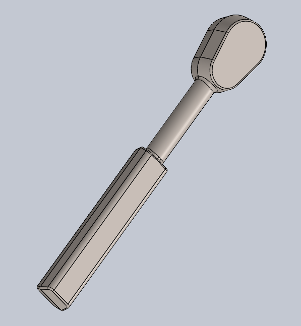
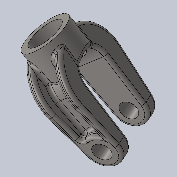
Stirling Engine in SolidWorks
Building SolidWorks proficiency by modelling a full Stirling engine assembly from provided drawings
Role: CAD Technician
|
Duration: 6 Weeks
|
Tools: SolidWorks
|
Context: College Project
|
Role: CAD Technician | Duration: 6 Weeks | Tools: SolidWorks | Context: College Project |
Project Overview
This project was part of Product Design and Modelling, a module built around developing practical CAD skills rather than open-ended design work. Working individually over six weeks, I modelled, assembled, and documented a Stirling engine from a reference design shown in class, ending up with a 20-part assembly (excluding fasteners) and a full 18-sheet drawing set. Each part was chosen to introduce a specific SolidWorks feature, so the brief worked less like a design project and more like a structured way to build up CAD skills from the ground.
Exploration/Discovery
Going into this module, my SolidWorks experience was limited to what I'd used in secondary school, since I'd since moved on to Fusion 360 at work and FreeCAD for my own projects. With a reference model shown in class as the target, I went through the drawing set first to get a sense of how the 20 parts fit together and roughly how complex each one would be, so I could plan an order to model them in rather than working straight through top to bottom. That read-through also made clear this was going to be less about engineering judgement and more about accurately translating dimensioned 2D drawings, materials, and tolerances into fully constrained 3D parts.
Design Process
Modelling the parts meant getting properly fluent with Hole Wizard and the Toolbox library for standard fasteners, since almost every part in the assembly needed accurately sized holes and hardware rather than generic ones. Several of the 18 drawings carried tight tolerances I had to model and dimension to exactly, and the parts themselves used real assigned materials, mostly brass and steel with a copper gasket, rather than just appearance overrides, so the model's mass properties stayed accurate rather than cosmetic. Getting the assembly's mates right mattered as much as the individual parts: with 20 components involved, the piston, displacer, connecting rod, and flywheel all needed to move together correctly as a mechanism rather than just look assembled. I also learned to build my own drawing templates and title blocks during the module, which I used across the sheet set.
Final Design
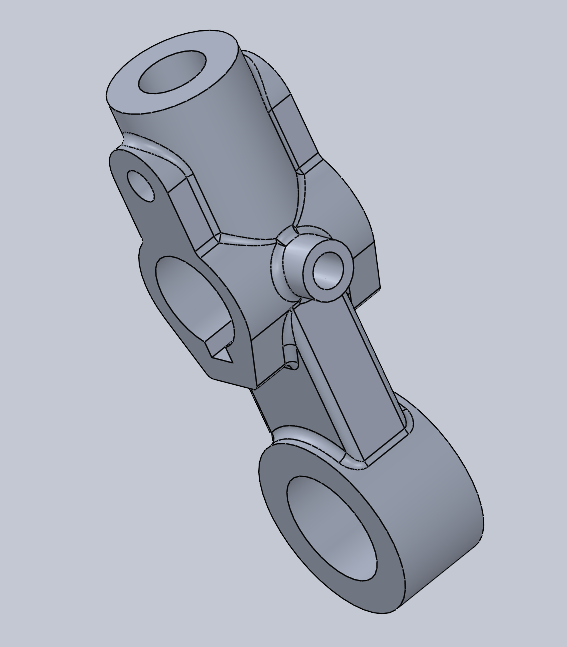
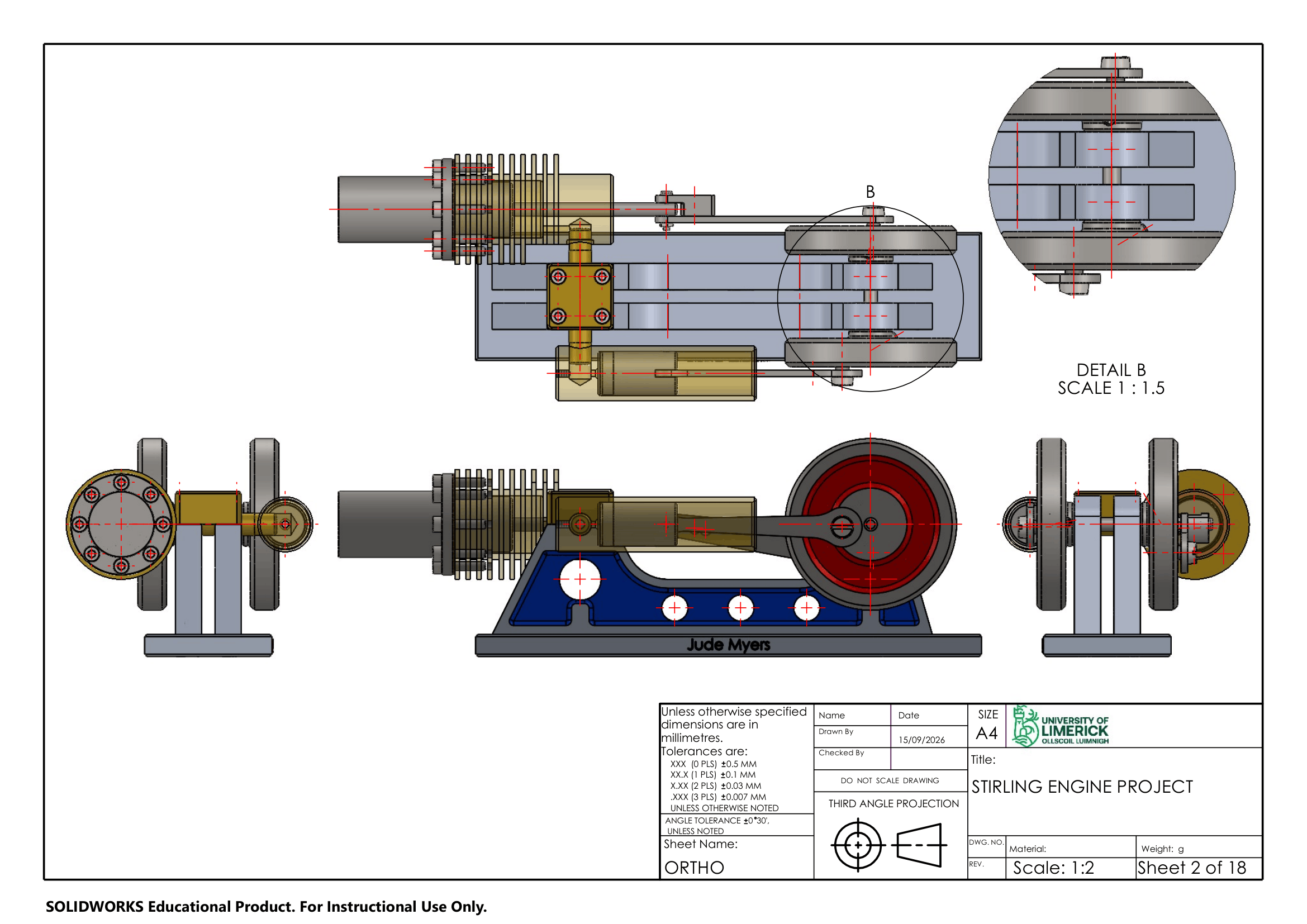
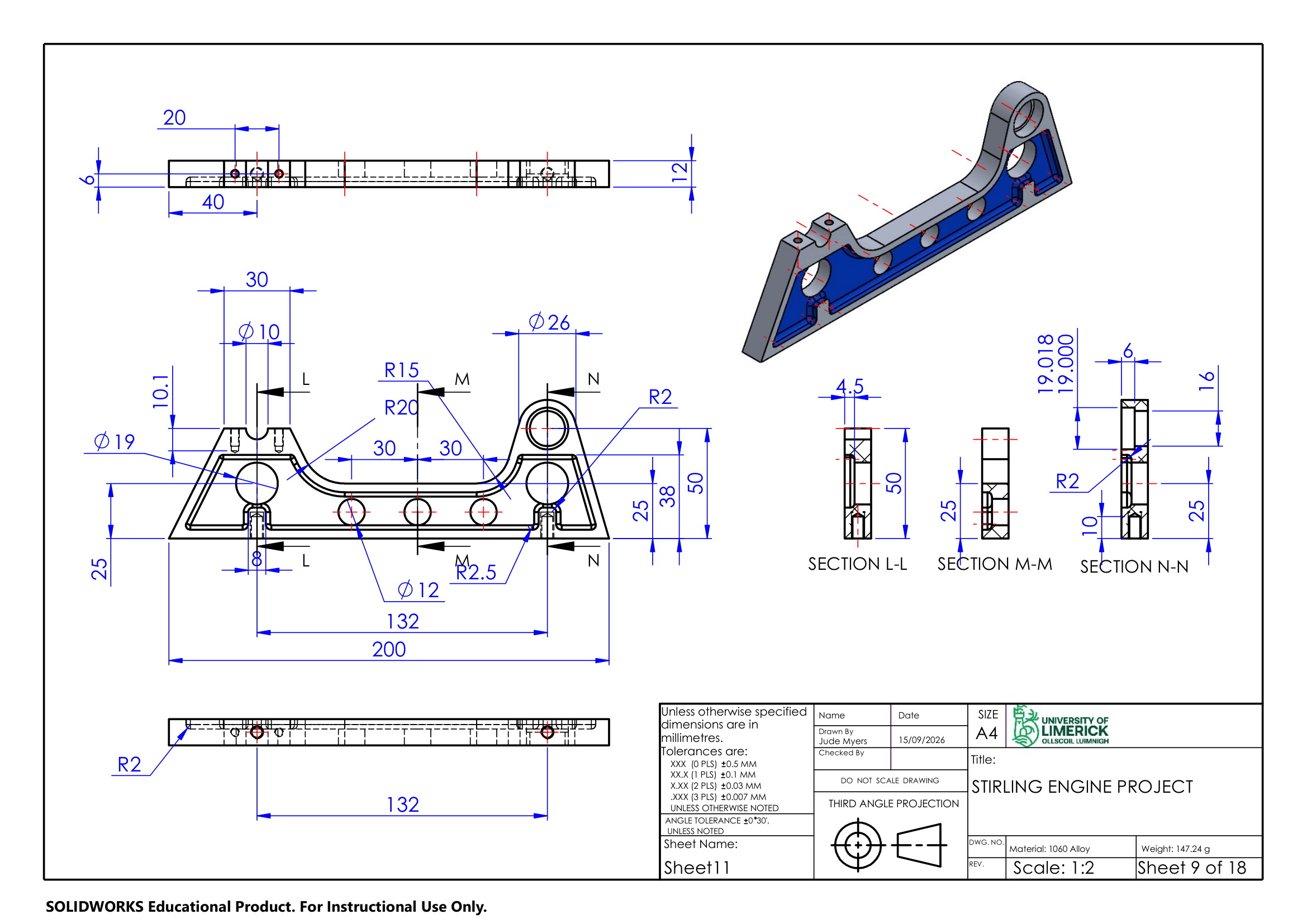
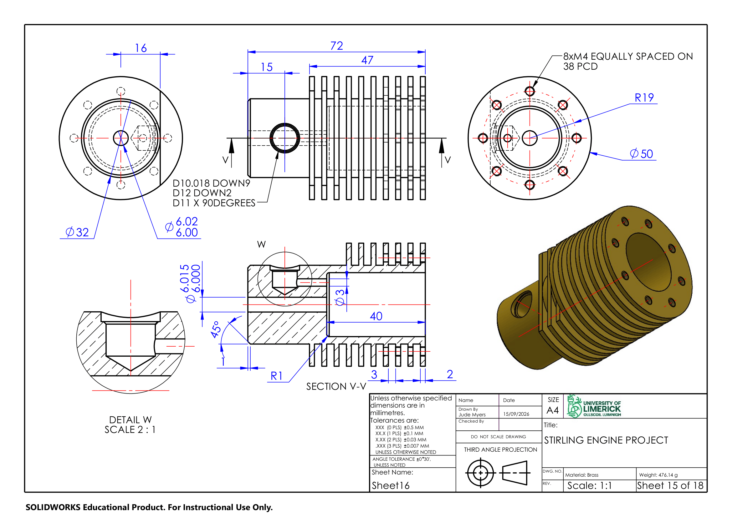
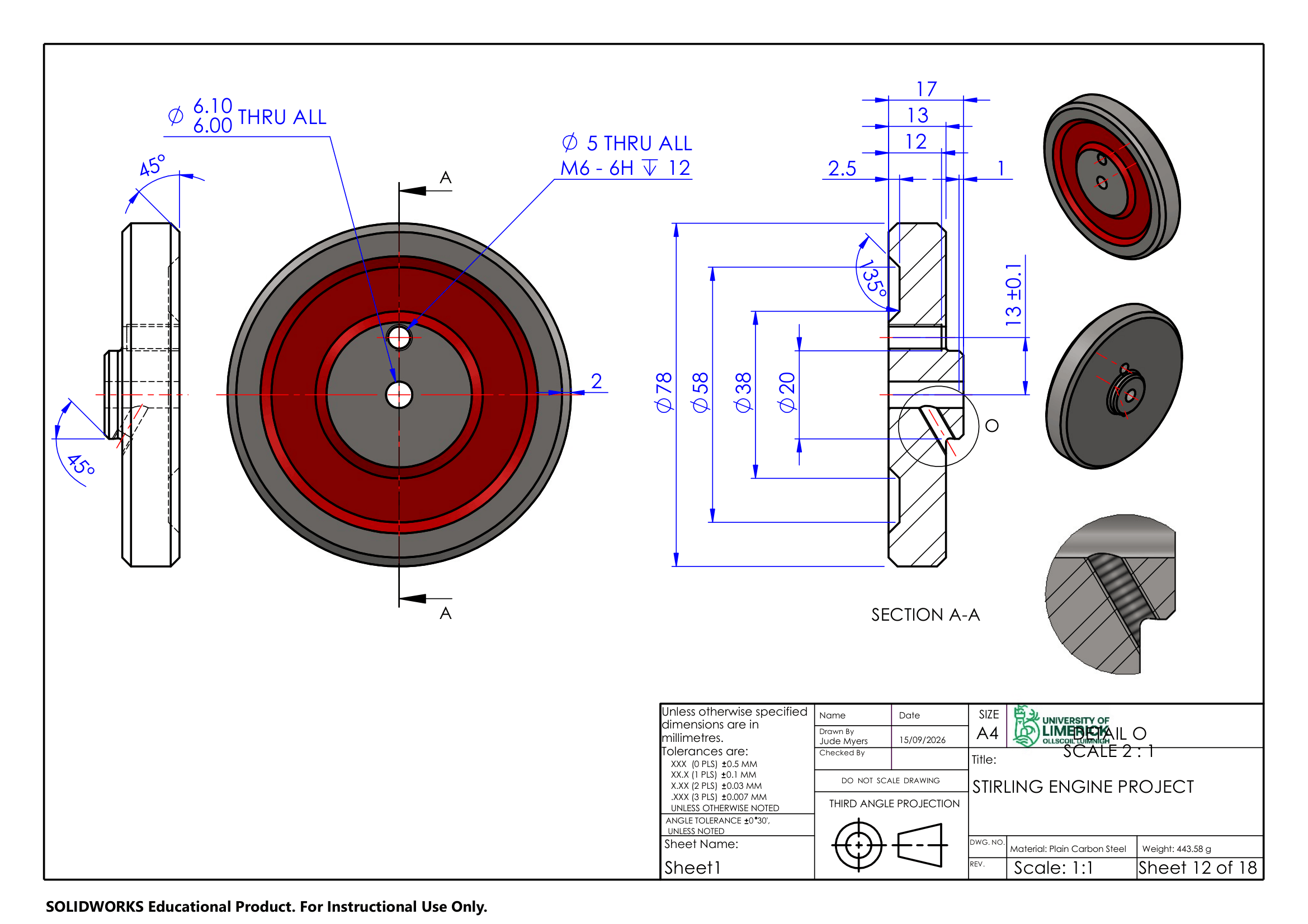
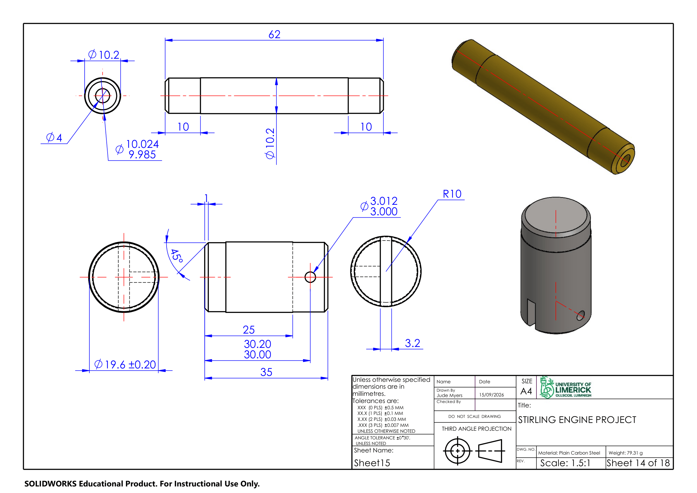
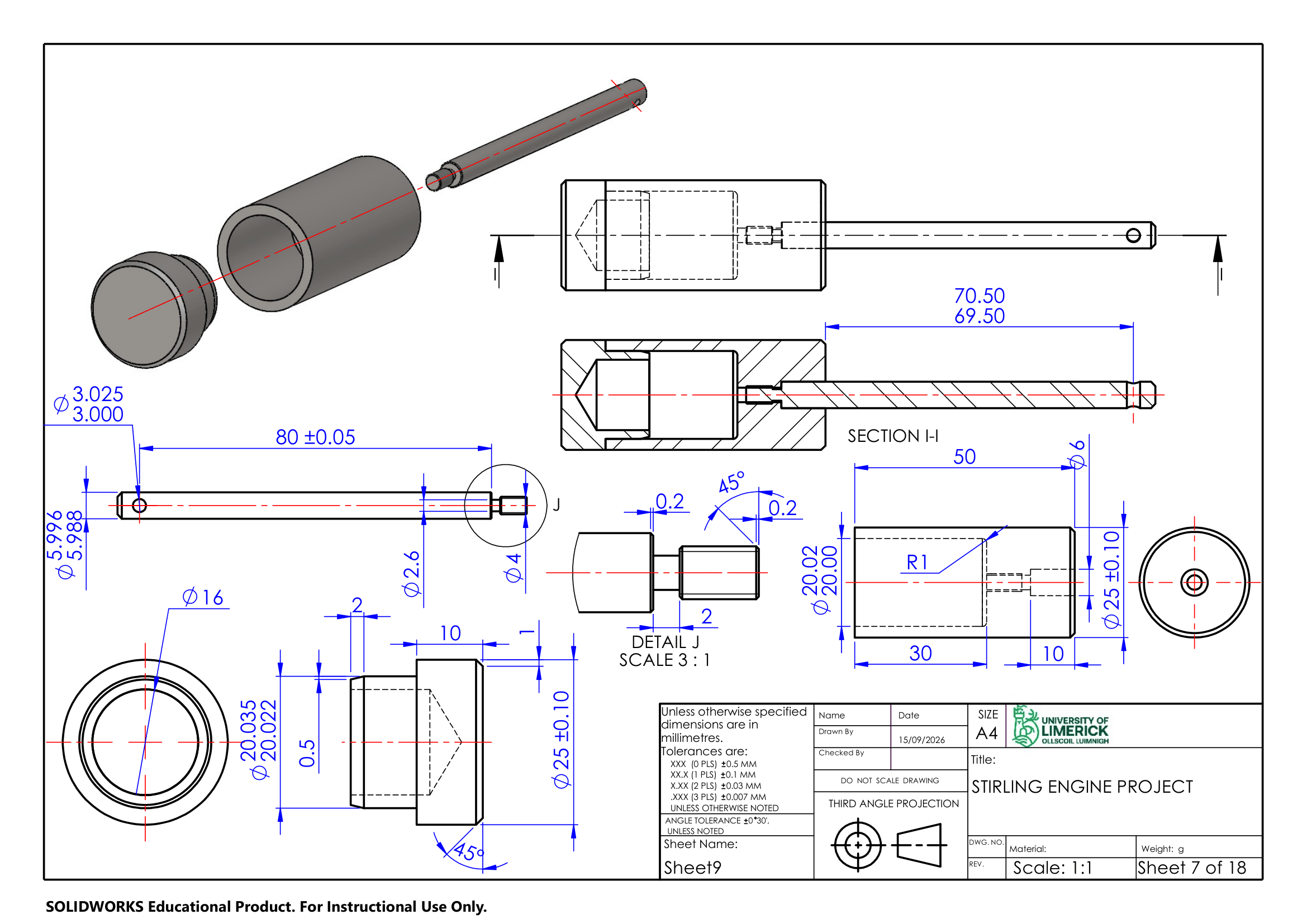
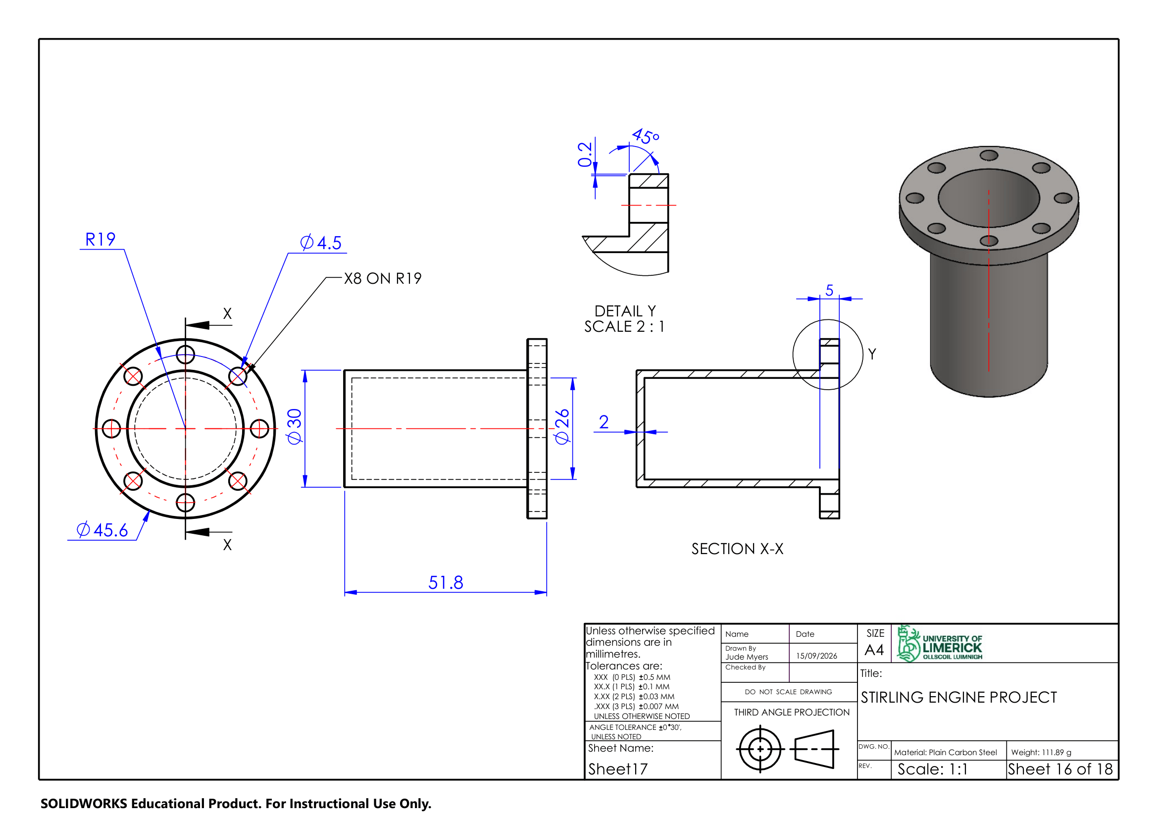
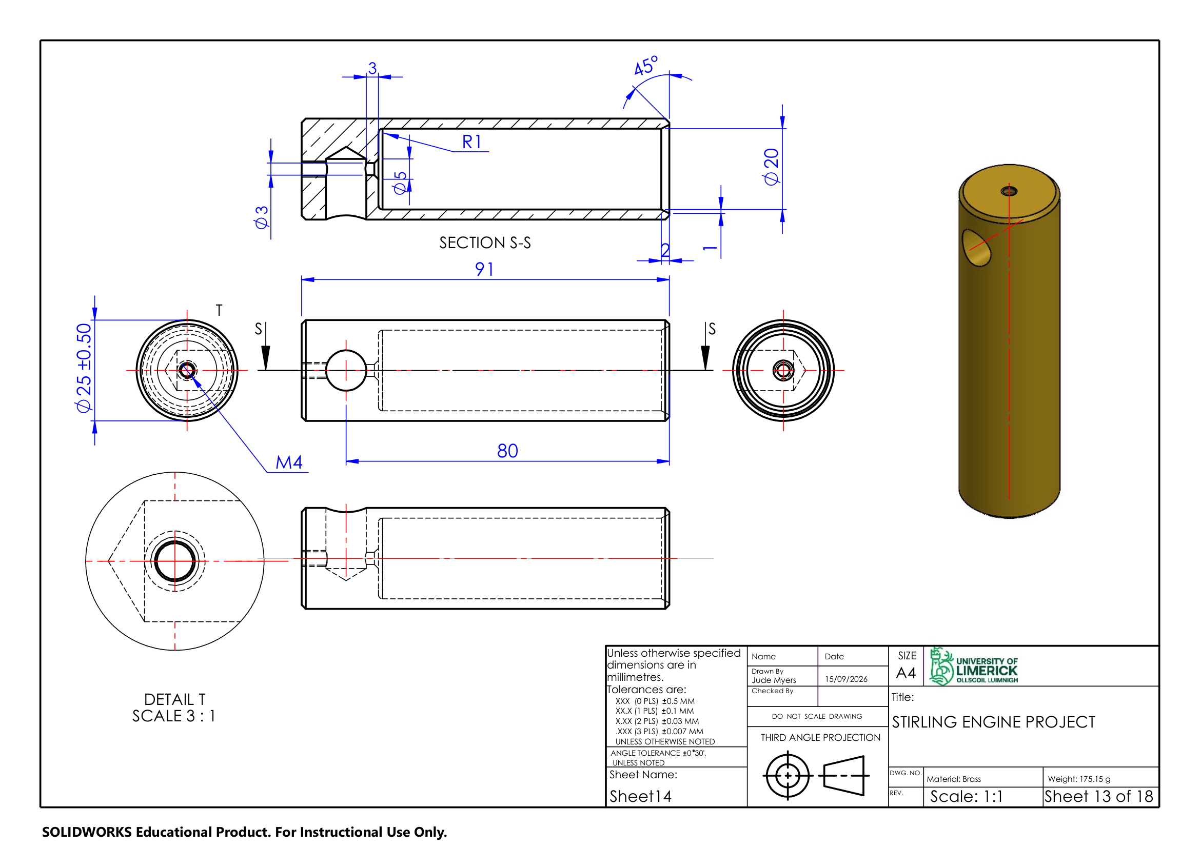
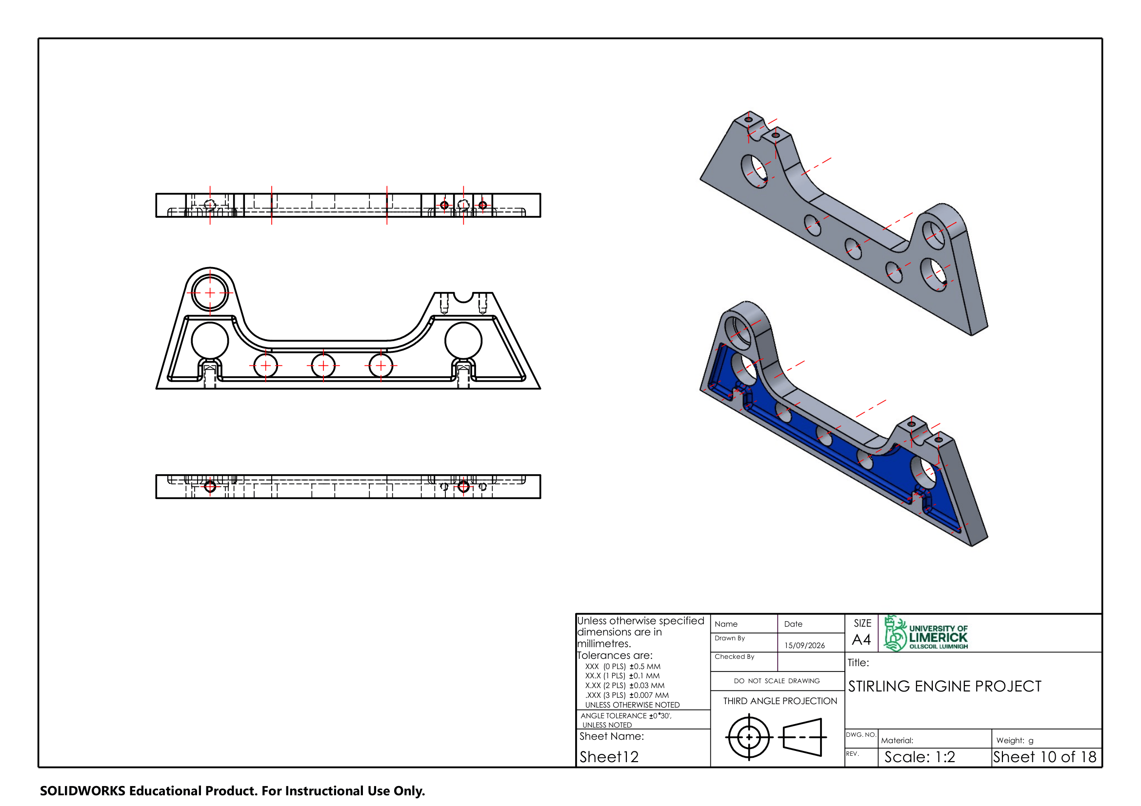
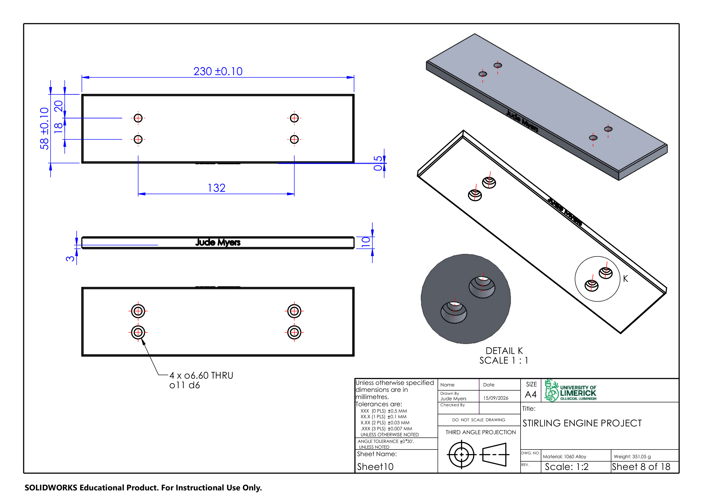
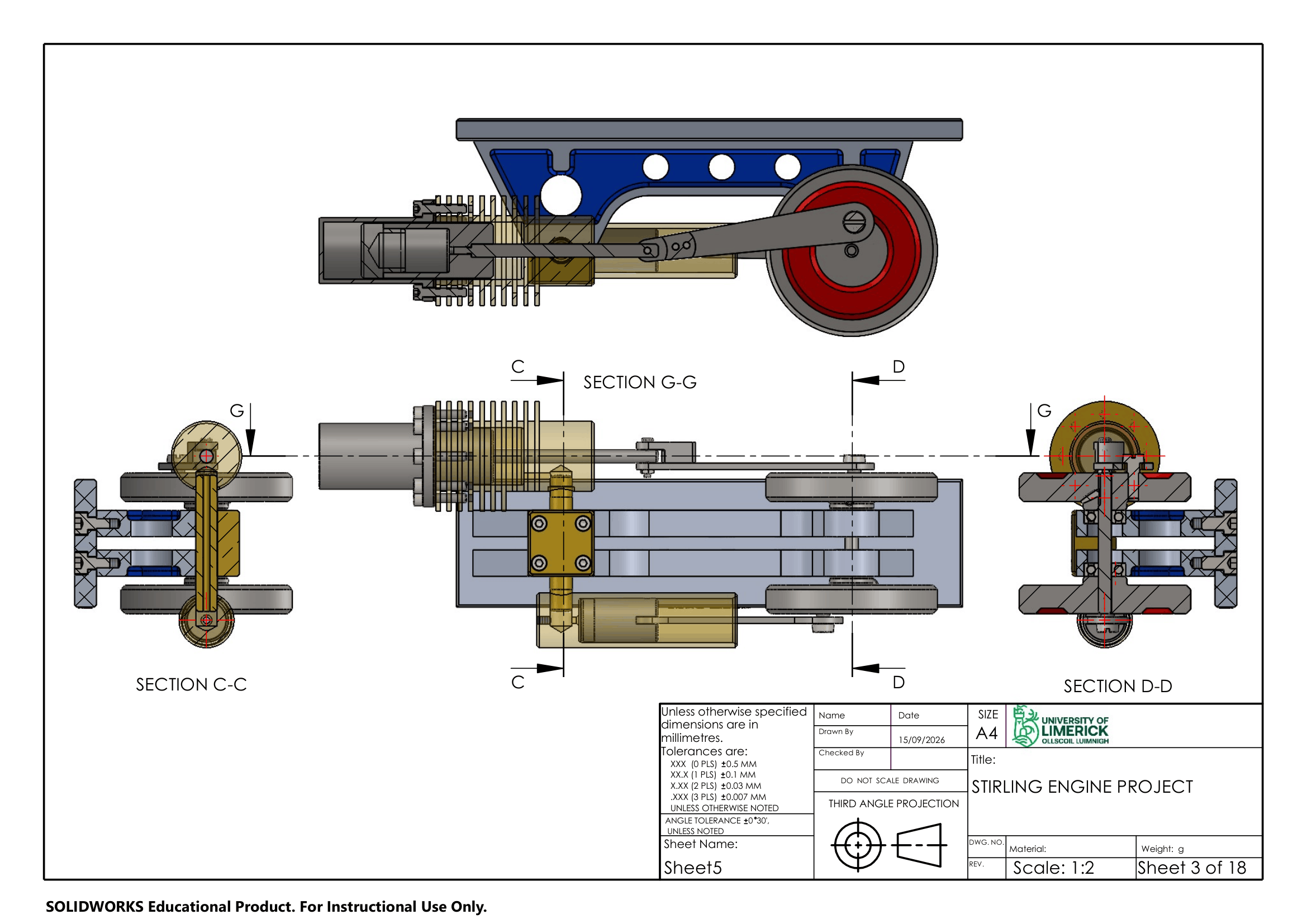
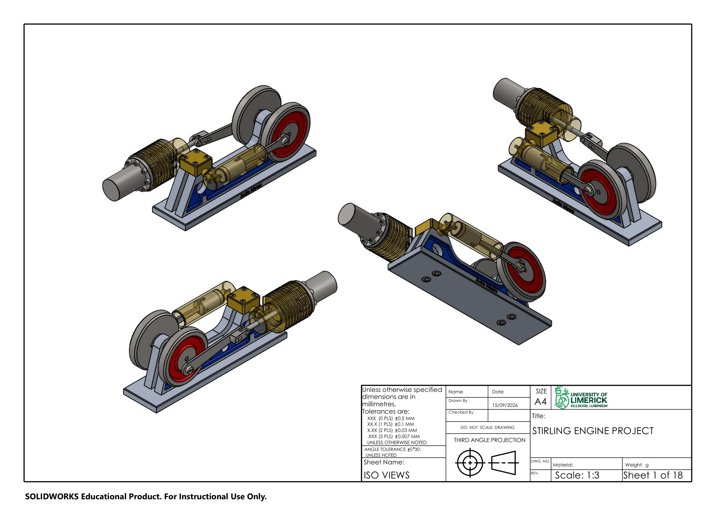
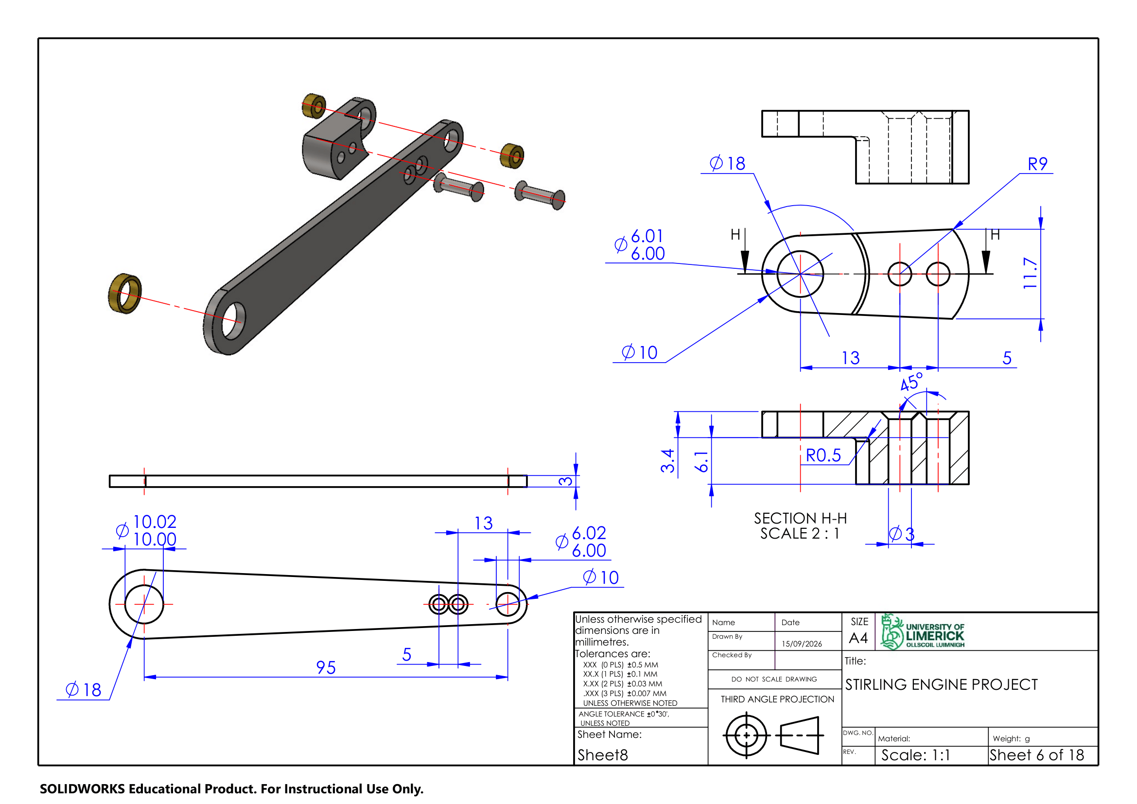
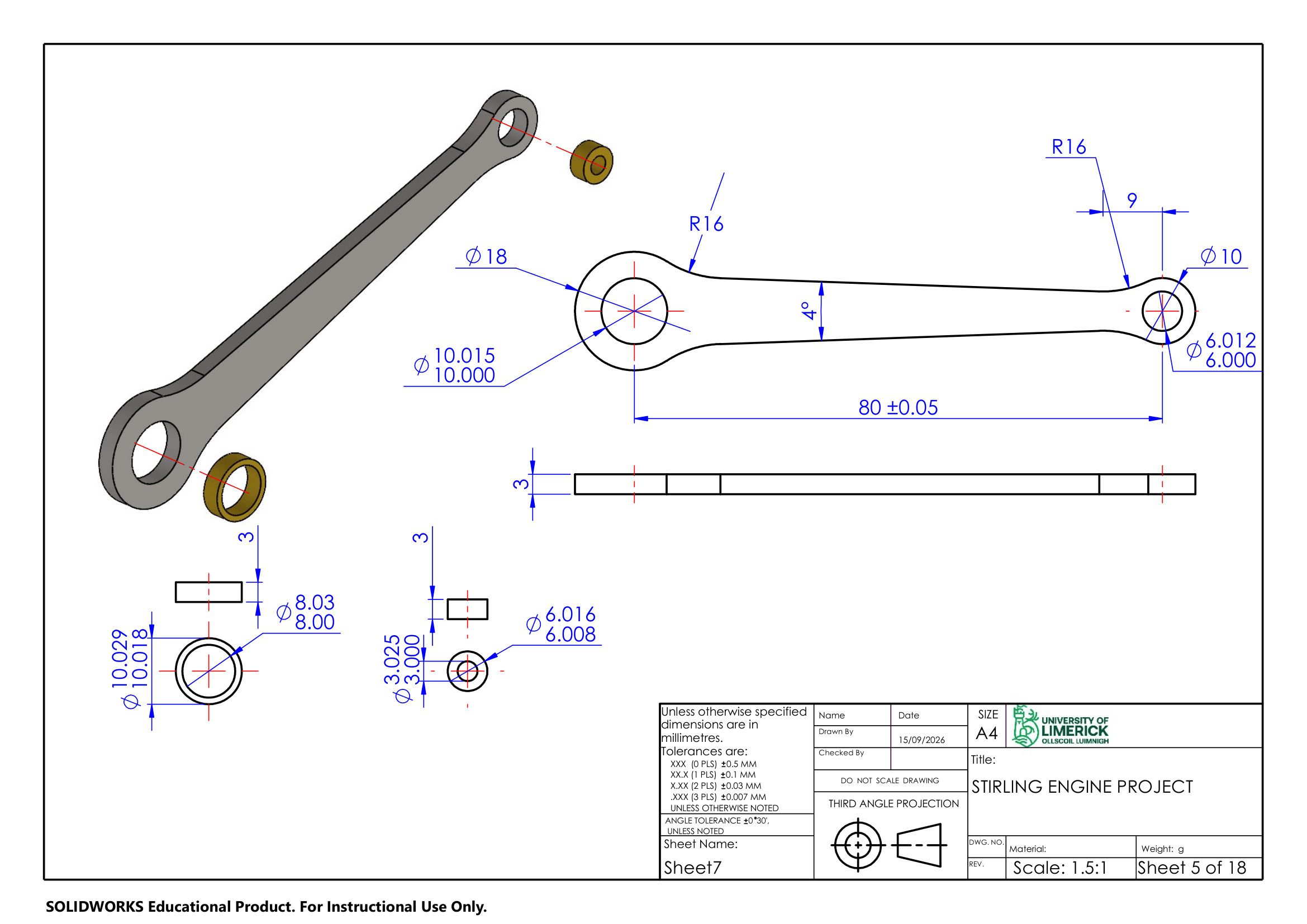
The finished assembly brings all 20 parts together into a fully mated SolidWorks assembly where the piston, displacer, connecting rod, and flywheel move as an accurate mechanism rather than a static render. I also built an exploded view animation of the full assembly exploding out and reassembling, shown at the start of this webpage. That's backed by a complete 18-sheet drawing set covering assembly views, section views like the cylinder's internal cross-section, and individual part drawings for components like the connecting rod and frame bracket, each carrying its own dimensions, tolerances, and title block. The gallery above shows a sample of the sheet set, the full drawing pack and all the other files are available through the blue button below.
Impact & Reflection
This project was CAD-only, no physical build, and with the whole module built around SolidWorks specifically, it was the biggest single push my fluency in the software got. I'd been getting by across three different CAD packages depending on context. SolidWorks only from secondary school, Fusion 360 at work, FreeCAD for my own projects. Modelling a 20-part assembly to exact tolerances, with materials and a fully working mate structure, forced me to get properly comfortable with the software most automotive and manufacturing employers actually expect. Working from someone else's reference design and drawing set, rather than my own sketches, also made me more careful about reading dimensions and tolerances correctly, which is a habit I don't think you can build any other way.
Practice Models